In the circuit diagram shown in the adjoining figure, the resultant capacitance between $P$ and $Q$ is:
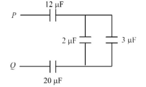 .
.
- A$47\,\mu\text{F}$
- B$3\,\mu\text{F}$
- C$60\,\mu\text{F}$
- D$10\,\mu\text{F}$
✓ Correct answer: B
Want the full step-by-step reasoning?
NewNcert › Physics › Electrostatic Potential and Capacitance
In the circuit diagram shown in the adjoining figure, the resultant capacitance between $P$ and $Q$ is:
.
Want the full step-by-step reasoning?
Question ID #437480 · NewNcert